Need custom hydraulic hoses delivered to your door?
Let our professional hydraulic hose technicians create your custom designed hydraulic hose assembly.
Select from or range of Gates Braided or Spiral hoses with working pressures to 6000 PSI.
Configure the following attributes with our step by step configurator
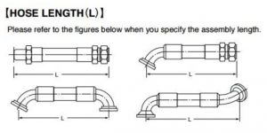
- Overall length
- Hose ends to suit your hose selected hose
- Hose protection – Spiral guard
- Burst protection – MDG41 compliant
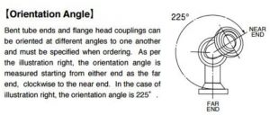
- Hose end orientation
All measurements are in millimetres.
Read more about the Gates Connected range and our hose manufacturing capabilities.

Custom Hose Builder – Braided Hose
Select from the following
- Hoses from 1/4″ through 2″
- Working pressures from 1175 PSI to 6000 PSI
- JIC, ORFS SAE 61 and 62, CAT flange, BSP, Metric light and heavy.
- Hose protection – spiral guard
- Burst protection – MDG41 Compliant
- Hose end orientation for combination 45° & 90° fittings
Working pressures
1/4″ – 6000 PSI | 3/8″ – 4800 PSI | 1/2″ – 4000 PSI
5/8″ – 3625 PSI | 3/4″ – 3125 PSI | 1″ – 2400 PSI
1 1/4″ – 1825 PSI | 1 1/2″ – 1300 PSI | 2″ – 1175 PSI
Custom Hose Builder – Spiral Hose
Select from the following
- Hoses from 3/8″ through 2″
- Working pressures either 4000 PSI or 6000 PSI
- JIC, ORFS SAE 61 and 62, CAT flange, BSP, Metric light and heavy.
- Hose protection – spiral guard
- Burst protection – MDG41 Compliant
- Hose end orientation for combination 45° & 90° fittings
Working pressures
EFG4K – 4000 PSI – 3/8″, 1/2″, 5/8″, 3/4″, 1″, 1 1/4″
EFG6K – 6000 PSI – 3/8″, 1/2″, 5/8″, 3/4″, 1″, 1 1/4″, 1 1/2″, 2″
Hose end orientation
Important – Please refer to the graphic on the right to ensure the hose end orientation is correctly specified.
When you choose two angled fittings, such as a 90° and a 45° fitting, we need to know how they should be installed
- Hose end 1 is the far end – hold end vertically down.
- Hose end 2 is the near end.
- Orientation and is measured clockwise and is the angular difference between hose end 1 and 2.
Important information for the designer
Custom Made Hose Assemblies are NON-RETURNABLE.
It is the hose designers responsibility to ensure that their custom hydraulic hose is suitable to the intended application. If the designer is unsure about the product selected they should consult the product information for that item or CONTACT US.
We recommend that the industry standard STAMPED process is followed when selecting replacement hose assemblies.
SIZE
> Internal diameter requirements will affect fluid velocity and outside diameter may also sometime be concern for routing purposes. When in doubt match existing specifications.
TEMPERATURE
> The maximum recommended hose temperature should never be exceeded, either in the fluid conveyed or on the exterior of the hose. Similarly special hose are available which will maintain flexibility at very low temperatures, always follow manufacturer guidelines.
APPLICATION
> Environmental conditions such as ultraviolet light, salt water, air pollutants, temperature, ozone, chemicals, electricity, abrasion and paint application will all negatively impact hose assembly life.
> Static Discharge can become an issue when non-polar liquids or mixtures including non-polar liquids are conveyed in non-conductive hose. A static charge will build and on discharge perforate the hose tube, to avoid this use conductive tube products when conveying non-polar, or mixtures of non-polar, liquids.
> Electrical Conductivity of hydraulic hose or conveyed fluids is an issue with equipment used to work around electrical lines. If hydraulic equipment is to be used around electrical lines, always use hydraulic hose rated as non-conductive.
> The cleanliness requirements of a final hose assembly will be determined by the system it is to be applied too. Always follow the equipment manufacturer’s recommended cleanliness standard.
> Be sure to select products which will meet any regulatory standards required in the application. Examples of these standards would include: SAE, USCG, EN/DIN, ABS, etc.
> Never place hose in a position where they are pulled on. Hose are designed to hold pressure and convey fluids, exposing them to axial loads will cause premature failure.
> Any special or unusual applications should always be approved by the hose manufacturer, otherwise additional independent testing may be required.
MATERIALS
> Permeation, or effusion, is the movement of a substance through the hose tube walls which may degrade the hose tube, cause cover blistering, or other undesired effects, and must be considered especially when conveying compressed gasses.
> Be sure to select a hose which is compatible and approved by the manufacturer for the fluid conveyed. Concentration, pressure, temperature and other factors may impact the compatibility of the hose and fluid.
PRESSURE
> The maximum working pressure of a hose assembly is the lowest working pressure of any component of the assembly.
> Hose should be sized with a working pressure equal to or above the maximum pressure encountered in a system. High frequency electronic transducers will be necessary to determine the maximum surge, or impulse, pressure in a system.
> If a hose assembly will be exposed to suction, be sure it is rated to hold the maximum suction and pressure in that portion of the system.
> Any time a hose assembly is to be exposed to external pressures, which may exceed the internal hose pressures, be sure to consult the hose manufacturer for recommendations.
ENDS
> Always use manufacturer approved couplings for hose assemblies. Be sure to select the appropriate end termination for a system working pressure and other requirements such as vibration resistance.
DELIVERY
> Always follow manufacturer recommendations for maximum fluid velocity within a hose. Excessive fluid velocity may cause excessive pressure loss, heat generation, hose movement or whipping, system noise, and hammer effects.


